- De
- En

In recent years, controllable first stages have emerged as the most promising concept for reusable launch vehicles (RLVs), thanks in no small part to the commercial success of the SpaceX Falcon 9 rocket. These first stages autonomously return to the launch site after multiple deceleration maneuvers (retro-propulsion). This approach is now being pursued by other spacefaring nations and holds the potential for significant cost savings in future launch systems. Numerical methods for flow simulations are an essential tool for predicting the thermal and mechanical stresses on the rocket when it executes complex maneuvers at high speeds. In order to facilitate the exchange in the scientific community, DLR provides a representative open-source geometry of a reusable launch vehicle to collaboratively explore the challenges associated these types of launchers.
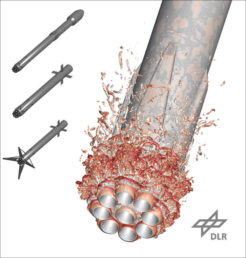
The image shows a simulation result of this RLV in unpropelled flight back to its landing site. Using hybrid RANS/LES simulations allows to resolve most of the turbulent vortices generated by the rocket nozzles and the launcher base, however, they require the use of supercomputers, in this case, CARO. By simulating the time-resolved flow field near the RLV, the researches at DLR can accurately estimate the unsteady mechanical loads on different parts of the launcher structure, e.g. the rocket nozzles, the launcher base and the landing legs. This helps to correctly size various launcher components and therefore increase the payload mass that can be delivered to orbit.
More information about the open-source launch vehicle, including the CAD geometry and current results, can be found at https://zenodo.org/communities/rfz-model. Different representations of the open-source model at various stages of flight are also shown in the picture. Top: Ascent phase. Middle: Controlled backward flight. Bottom: Landing phase with extended legs.
DLR Institute of Aerodynamics and Flow Technology (Braunschweig/Göttingen), 2023

The image shows the turbulent vortex shedding at the rocket base in backward flight at Ma = 0.85 and an angle of attack of 5°. The depiction on the left shows the three launcher configurations during ascent (top), controlled backward flight (middle) and landing (bottom) with the legs extended.

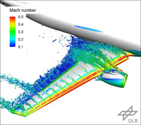
Resolved turbulent structures on NASA Common Research Model in high-lift configuration at flow conditions near maximum lift.
Highly accurate numerical simulation tools are indispensable for the design of future climate-friendly commercial aircraft. During the takeoff and landing phases of such aircraft, flaps are extended at the leading and trailing edge of the wing to increase the achievable lift of the airfoil in low-speed flight (high-lift configuration). This results in complex flow phenomena with local separations and interactions with the engine, which are difficult to capture using classical numerical simulation approaches (turbulence models). For this reason, simulations are increasingly being used that switch to a complex turbulence-resolving large-eddy simulation (hybrid RANS/LES), at least in areas of particularly complex flow.
With the help of CARO, hybrid RANS/LES can be used for the first time for complete 3D aircraft configurations in order to evaluate the capabilities of this approach on industry-relevant flow cases and to derive possible further developments. One such investigation took place at the international 4th AIAA CFD High Lift Prediction Workshop, where the NASA Common Research Model shown in the figure was simulated in high lift configuration (CRM-HL) up to high angles of attack beyond maximum lift. It was shown that the high-precision resolution of turbulent vortex structures, which arise for example at the wing root, at the engine and at the trailing edge of the wing (see figure), enables a significantly improved prediction of important aerodynamic parameters such as lift, drag and pitching moment.
DLR Institute of Aerodynamics and Flow Technology (Braunschweig/Göttingen), 2023
A key component in reducing an aircraft’s fuel consumption and thus CO2 emissions is minimizing its drag. Frictional drag, which is caused by characteristic physical effects in a very thin layer in the immediate vicinity of the aircraft surface, contributes about 50% to the flight resistance. In this boundary layer there are different types of flow, laminar flow and turbulent flow. The laminar flow is very calm and low in drag, while the turbulent flow is very turbulent, highly swirled and generates high drag. Nowadays, almost all commercial aircraft have exclusively turbulent boundary layers. To significantly reduce drag, future commercial aircraft should be designed with laminar flow components that are as extensive as possible. To accomplish this, one must find out at which flow conditions and states the initially laminar flow transitions to turbulent and in which regions of the aircraft surface this laminar-turbulent transition occurs. In addition, it is necessary to know in which way the transition occurs, because there are also different types of the transition.
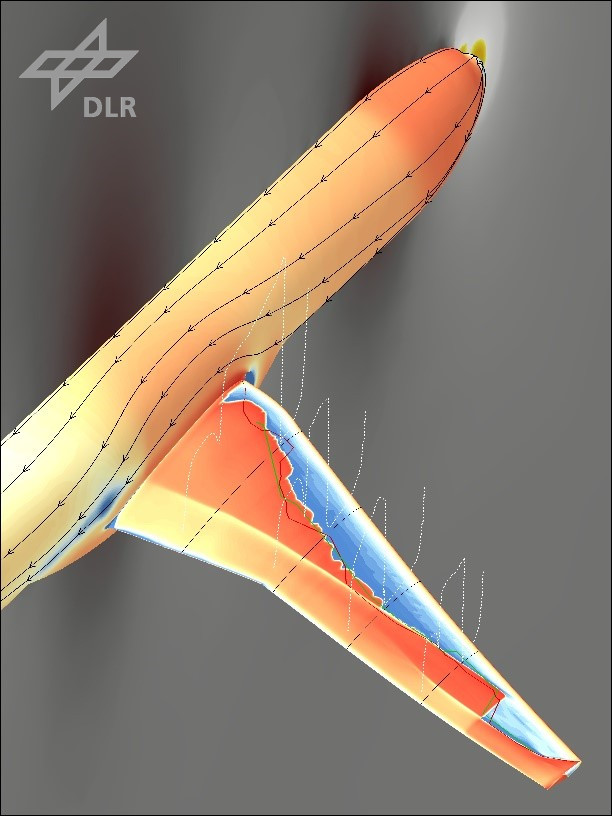
In order to make such predictions, physical models have been derived and mathematically formulated in a suitable way to produce simulation results for the fundamental flow equations, the Reynolds-averaged Navier-Stokes (RANS) equations, which also include the information about the transition, within the framework of large, HPC-based calculations. In the result image, the transition line on the surface of the NASA Common Research Model with Natural Laminar Flow (CRM-NLF) is shown at the transition of the laminar frictional stresses (blue) to the turbulent frictional stresses (orange) compared to the measured transition lines (red, green). The dashed white lines show the exceedingly large increase in frictional stresses at the laminar-turbulent transition in four wing sections.
The calculations were performed on the HPC cluster CARO at DLR in Göttingen.
DLR Institute of Aerodynamics and Flow Technology (Braunschweig/Göttingen), 2023

Laminar-turbulent transition on the wing of the NASA Common Research Model with Natural Laminar Flow (CRM-NLF): the dashed white lines show the sharp increase in frictional stresses at the laminar-turbulent transition.

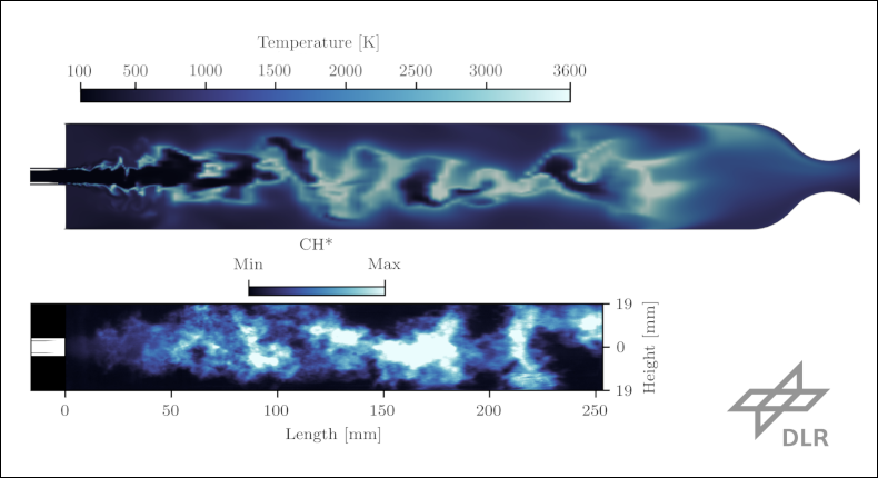
30 million node LES simulation of the combustion process within the BKN combustion chamber (top) compared to transient optical flame imaging from combustion experiments (bottom).
Methane has become one of the most promising rocket fuels for future space launchers. To aid the overall research activities on methane-oxygen combustion in rocket engines, DLR Lampoldshausen has developed the experimental combustor “BKN”, which has a large optical access window allowing for the visualization of the flame and combustion processes. Numerical simulations have been used side by side during the design process of BKN, aiding in its development. Subsequent simulations have been able to run in tandem with the chamber’s operation, utilizing the experimental data generated for comparison and validation.
The flow in rocket combustion chambers such as BKN present several challenges for numerical simulations. The combustion processes take place in the absence of nitrogen, have temperatures ranging from 100 K to 3700 K, have cryogenic inflow conditions requiring real gas equations of state, and velocities ranging from only a few meters per second within the injector up to Mach 3 and above within the nozzle. These conditions bring existing physical models to their limits and pose high demands on computational resources.
Numerous simulations of BKN have been conducted in support of the development of the experimental hardware. These include the characterization of the flow through injector features used to decouple the chamber from the feed system, the determination of the influence of the window cooling inflow on the flame shape, and the identification of favorable mass flow rates for experimental activities to gain a clear view of the flame and minimize heat loads on the window.
The CFD activities to date are culminating in a 30 million node LES simulation of the combustion process within the chamber, which can be compared to transient optical flame imaging from the combustion experiments, such as that for CH* radiation shown in the figure.
These simulations have been made possible by the newly-built HPC cluster CARO at DLR in Göttingen.
DLR Institute of Space Propulsion (Lampoldshausen), 2023